LED Knight Rider Using 4017 and 555 IC's

LED Knight Rider Using 4017 and 555 IC's

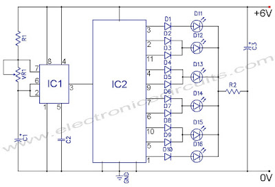
In this 4017 Knight Rider circuit, the 555 is wired as an oscillator. It can be adjusted to give the desired speed for the display. The output of the 555 is directly connected to the input of a Johnson Counter (CD 4017).

LED Knight Rider Using 4017 and 555 IC's, circuit, electronica,


PARTS LIST
R1 22kΩ
R2 220Ω
VR1 50kΩ PRESET
C1 1µF 16V
C2 0.01µF (103)
C3 10µF 16V
D1 – D10 1N4148
D11 – D16 LED
IC1 NE555
IC2 CD4017

LED Knight Rider Using 4017 and 555 IC's, circuit, electronica,


The input of the counter is called the CLOCK line. The 10 outputs become active, one at a time, on the rising edge of the waveform from the 555. Each output can deliver about 20mA but a LED should not be connected to the output without a current-limiting resistor (220Ω in the circuit above).

LED Knight Rider Using 4017 and 555 IC's, circuit, electronica,

CD4017
LED Knight Rider Using 4017 and 555 IC's, circuit, electronica,

NE555

The first 6 outputs of the chip are connected directly to the 6 LEDs and these “move” across the display. The next 4 outputs move the effect in the opposite direction and the cycle repeats. The animation above shows how the effect appears on the display.

Using six LEDs, the display can be placed in the front of a model car to give a very realistic effect.

The outputs can be taken to driver transistors to produce a larger version of the display.

Arduino Project Knight Rider

Arduino Project Knight Rider

Arduino Project Knight Rider, circuit, arduino, microcontroller,

In this tutorial, eight LED's are interfaced to the Arduino Uno board.

A program is then loaded to the Arduino that will turn the eight LEDs into a "Knight rider" display.

Components

Besides a breadboard, Arduino Uno and USB cable, you will need:
8 pcs 470 ohm resistor (yellow - violet - brown)
8 pcs 5mm red LED
9 Wire links

Circuit Diagram
The circuit diagram is shown below. It is simply eight LEDs interfaced to the Arduino pins 2 to 9.

Arduino Project Knight Rider, circuit, arduino, microcontroller,

Building the Circuit
Place the LEDs next to each other in the breadboard so that the anode (longer lead) is at the left and the cathode is on the right.

Insert the 470 ohm resistors connecting one lead to the LED's cathode and the other to the top rail.

Join the anodes of the LEDs to pins 2 to 9 of the Arduino from left to right using single-core wire. Join the top rail to one of the GND pins of the Arduino.

When finished building the circuit, connect the Arduino to the PC via the USB cable.

Loading the Program
The Knight Rider program listing is shown below. Copy it and pasted it into the Arduino IDE.

/*
  Knight Rider
  Knight rider display on 8 LEDs
*/

void setup() {
    // set up pins 2 to 9 as outputs
    for (int i = 2; i < 10; i++) {
        pinMode(i, OUTPUT);
    }
}
// function to switch all LEDs off
void allLEDsOff(void)
{
    for (int i = 2; i < 10; i++) {
        digitalWrite(i, LOW);
    }
}

void loop() {
    // move on LED to the right
    for (int i = 2; i < 9; i++) {
        allLEDsOff();
        digitalWrite(i, HIGH);
        delay(200);
    }
    // move on LED to the left
     for (int i = 9; i > 2; i--) {
        allLEDsOff();
        digitalWrite(i, HIGH);
        delay(200);
    }
}

Load the program to the Arduino and if the circuit was built correctly, your knight rider circuit will start operating.

The following video shows what you will achieve:

Easy Build a Circuit on Breadboard Use LED

Easy Build a Circuit on Breadboard Use LED

Easy Build a Circuit on Breadboard Use LED, circuit, electronica,

This tutorial shows you how to build a very simple circuit which lights up a single Light Emitting Diode (LED).

Componenct:
1 pcs 1k resistor (1000 ohm, brown - black - red)
1 pcs 5mm red LED

You will also need:
A breadboard
Breadboard wire links
9V battery (nine volt battery)
Battery clip

How the Breadboard and Circuit Works
The red lines in photo below show how the breadboard is connected internally. The figure shows only some of the vertical connections, they repeat as shown.

Easy Build a Circuit on Breadboard Use LED, circuit, electronica,

The top and bottom parts of the breadboard are identical and have four horizontal connecting strips. The middle of the breadboard has vertical connecting strips separated by a horizontal channel in the middle.

Each individual red line or connecting strip is electrically isolated from every other strip.

Any component lead that is plugged into a hole or "tie point" of the breadboard will be connected to whatever is plugged into a hole of the same connecting strip as marked in red in the photo.

The video below shows the circuit in action:

Easy Build RF Receiver / Transmitter Pair (27 MHz)

Easy Build RF Receiver / Transmitter Pair (27 MHz)

Easy Build RF Receiver / Transmitter Pair (27 MHz), circuit, electronica,

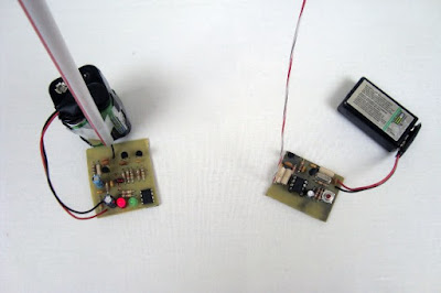
In this article we will build a simple rf receiver module that works at 27 mhz and turns on an LED anytime the signal from the transmitter is detected. A very simple idea, but as you will soon find out, a lot goes into making it a reality. We'll be making our own PCB for this circuit, so get out the ferric chloride and copper clad PC board.

Purpose and Overview Of This Project
The goal of this project is to make an RF receiver front end to capture the 27 MHz signal that we're expecting, connect that to two amplifier stages and then to use the originally transmitted signal to turn an LED on. This processs is very much the opposite of how the transmitter worked.
The front end receiver will be a very old regenative design that has been used for decades. The amplifier stages will be single transistor amplifiers that basically rail the signal between power and ground. The final part is a 555 timer which will be used as a comparator which will tell us whether our signal has made it through or not by lighting up a green LED.

Parts
PC Board
Toroid Core (AL=25)
3x 2N2222 Transistors
1x 555 Timer
2x 2.2MΩ Resistor
2x 180kΩ Resistor
2x 100kΩ Resistor
4.3kΩ Resistor
560Ω Resistor
2x 100Ω Resistor
100uF Capacitor
4.7uF Capacitor
3x 0.1uF Capacitor
2.2nF Capacitor
47pF Capacitor
27pF Capacitor
1x 5mm Red LED
1x 5mm Green LED
Magnetic Wire (AWG 24/26)
Antenna Wire (AWG 26/28)
+9v Battery Connector
Ferric Chloride
Clothing Iron
Solder
Soldering Iron

Parts List Details
Most of the parts in this project are discrete passive componenets, however the few active components are described in more detail below.

PC Board
We will make our own PCB for the receiver so that we can have exact control over all the connection lengths and parts used. 27 MHz is pretty low frequency so there's actually not too too much to worry about in terms of performance degradation.

6 Turn Inductor Toroid Core
The toroid core and magnetic wire will be used to make a small inductor. It's very important that your ferrite core is AL=25 otherwise the inductance will be off and the receiver won't work.

2N2222 Transistors
We will use 2N2222 general purpose transistors as part of our front-end for the receiver and for the amplifier stages.

555 Timer
The 555 timer will be used as a comparator and LED driver. The input voltage from the receiver will get compared using the 555 timer's input pins and the green LED will either be driven or not. The red LED driven by the 555 timer tells you the 555 timer is on and functioning.

Schematic Overview
The schematic for this project flows naturally from left to right. Beginning at the antenna and the regenerative receiver front-end, then flowing through the amplification stages and then into the 555 timer.


Schematic Specifics

Front-End Regenative Receiver
This is a very common regenerative receiver front-end that you can find in circuits all over the web. I tailored the parts used to what I had laying around, generally you can tweak part values a little bit, with the exception of L2 and C2 which are your tuning circuit (tank circuit) for 27.145 MHz.

Amplifier Stages
Two amplifier stages exist in the middle of the schematic. They are used to 'rail' the signal back to its square-wave digital form of either +5v or +0v. I'm pretty sure that these amplifiers could be tweaked to get better performance, however the current design should work well enough for our requirements.

555 Timer Receiver Comparator
The amplified signal makes its way to the 555 timer in the form of its original square wave where this 555 timer uses the voltage detected with internal comparators to create an output that turns on the green LED.

The video below shows the circuit in action:

555 IC To Build LED Flasher

555 IC To Build LED Flasher


Components

In addition to a breadboard, wire links, 9V battery and battery clip, you will need:
10k resistor (brown - black - orange)
4k7 resistor (yellow - violet - red)
1k resistor (brown - black - red)
100uF Capacitors
10n (0.01uF) Capacitors
NE555 IC

5mm red LED

Circuit Diagram

The circuit diagram is shown below. Note the following:
  1. The connection point for the positive terminal of the 9V battery is displayed as a circle at the end of a line with the label "+9V". This is just another way of showing where to apply power to the circuit.
  2. The 0V or "GND" of the circuit is shown as an inverted triangle at the bottom of the circuit. This is where the negative lead of the battery must be connected.
  3. The schematic symbol for the 555 timer IC is not drawn to the layout of the physical 555 IC. I.e. it does not have pins 1 to 4 on one side and pins 5 to 8 on the other. Schematic symbols for IC's are often laid out differently to the physical IC. This makes it easier to read the schematic diagram. Even though the pins are in different places in the schematic, they still have the correct pin numbers and names as the physical IC.

This picture shows a top view of the physical 555 timer IC with pin numbering. Compare it to the schematic symbol.


Building the Circuit

Plug the 555 timer IC into the breadboard across the middle insulating channel. None of the IC's pins will be shorted out because of the middle insulating channel. Using wire links, connect pin 8 of the IC to the top rail and pin 1 of the IC to the bottom rail. Get a wire link ready to connect between pins 6 and 2 of the IC.

Use the wire link to join pin 2 of the IC to pin 6. Get the 10nF capacitor ready and some wire links.

Connect one pin of the 10nF capacitor (C2) to pin 5 of the IC and the other pin of the capacitor to the bottom rail. This is done using two wire links in the photo. Get wire links ready to connect pin 4 of the IC to the top rail.

Use wire links to connect pin 4 of the IC to the top rail. In the photo, three links are used to do this. Get resistors R1 (4k7) and R2 (10k) ready.

Connect the 10k resistor (R2) between pins 6 and 7 of the IC. Connect the 4k7 resistor (R1) between pin 7 of the IC and the top rail. Get the 100uF capacitor ready.

Connect the positive lead of the 100uF capacitor (C1) to pin 2 of the IC and the negative lead to the bottom rail. Get the LED and the 1k resistor ready.

Connect the 1k resistor (R3) to pin 3 of the IC. Connect the other pin of the resistor into a free connecting strip of the breadboard. Connect the anode of the LED to R3 and the cathode of the LED to the bottom rail.

Check the circuit that you have built against the schematic diagram. Go around the IC and check that each pin is connected to what the schematic says it must be connected to.

If you are sure that your circuit is correct, connect the positive lead of the 9V battery to the top rail and the negative lead to the bottom rail and watch the LED flash on and off.

Try a different value capacitor for C1 to see the rate that the LED flashes change. E.g. try a 10uF capacitor to see the flash rate speed up.

Make a Timer With IC 555

Make a Timer With IC 555


Make the timer electronically can use the NE555 IC is designed specifically as a timer or multivibrator. Timer NE555 IC made it very simple and operated using a flexible DC voltage source of 4.5 VDC to 15VDC making it easier for us in the paint the voltage source to the timer. Timer NE555 IC made using the time setting has the timing based on the charging time of capacitor in the tank circuitnya. The larger the capacity of the capacitor is used then the longer timingnya. Basically make the timer using IC NE 555 555 timer IC is operating as monostabil multivibrator.

The 555 Timer IC is an IC timer that works based on a series of tank RC circuit and comparator strung together with digital component (R-Sflip flip-flop). The 555 timer IC first produced by Signetics i.e. type SE-555 who works at-55 ° C to 125 ° C and NE-555 who works at 0 ° C to 70 ° c. Then 555 manufactured with different designs include LM555, 556 (dual version), and the LMC-555 (CMOS version). The 555 timer IC is operating with dc power supply + 5v to + 18V with temperature stability of 50ppm/° C (0.005%/° C). The 555 timer IC output can be either a current sink/source up to 200mA. The 555 timer IC is compatible with TTL components, CMOS, op-amp, transistor and other linear IC types.